How I Learned to Write Electrical Engineering Specifications
About nine months ago, when I was still working at Microsoft as an electrical engineer on the Surface team, my manager asked me to write a specification for the project I was working on.
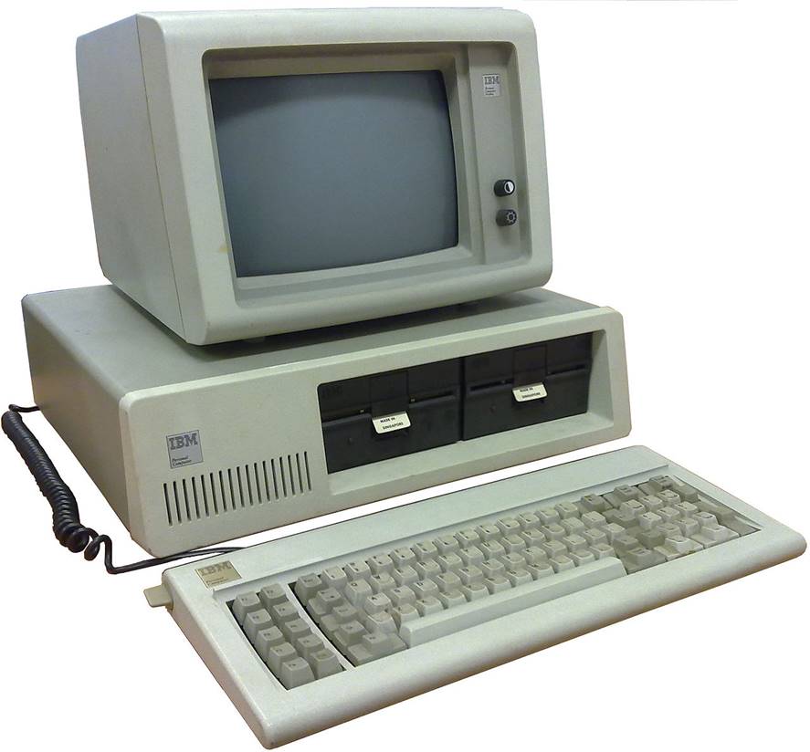
Figure 1: My teacher. Photo by Ruben de Rijcke
I was surprised by her request since most specifications (known also as “specs”) were written by engineers with much more seniority than me. The systems engineer responsible for my project had just quit, and because I was my team’s expert on my project, my manager was asking me to fill in for the departed systems engineer. I accepted, without fully understanding what I was getting myself into.
The more I thought about my new assignment, the more I started to worry. My project was a brand-new subsystem for our product, increasing the stakes on me. I kept starting at my office’s ceiling, and wondering: How does one write a specification? What exactly is the difference between a good specification, and a bad one? Writing specifications is a pretty important task, so why did I not learn anything about that in school? Did I miss a class?
This was not the first time I was looking back on college and doubting myself. Every time I had to learn on the job, I kept asking myself: “Why don’t I know this already? Did I miss something at Stanford?”. I had gone to a good school, and studied under professors who could charge hundreds of dollars an hour consulting in the industry, so how come I did not know how to do so many of the seemingly basic tasks a junior engineer was expected to do? So, it went on and on:
EMI testing – why don’t I know this already?
PCB manufacturing – why don’t I know this already?
Flexible circuit boards – why don’t I know this already?
A week after I had received my new assignment, it became clear to me that learning how to write a specification was going to be my hardest learn-on-the-job experience yet. Why? Because I was actually having an unlearn-on-the-job experience.
Back during school, and when I first started working, I used to think that writing specs was a useless exercise. What even was the point? Just design your system in your head, talk it through with others if you need to, and go build it. How could you even know all about your system before you start building it anyway? Any spec you could write would just be incomplete and not good. Writing specs was an unnecessary, bureaucratic task best to be avoided. Time spent on doing “paperwork” would be better used by actually building your product.
The sentiment above is still common in the technology industry, which I think is a shame. After three years in the industry, I have changed my mind, and now believe that a having good specs is critical for making your project a success.
Table of Contents
What even is a good specification, or the Huaqiangbei test
Trying to find the shoulders of giants
Lesson 1: Write your table of contents carefully
Lesson 2: Maintain a systems-centric view of your design, at all levels
Lesson 3: Clearly capture the interfaces within the design
Lesson 4: Do not mix implementation with specification
Lesson 5: Follow good electrical specification practices
Lesson 6: Think of how you can support the reader
Wrapping up, and further resources
What even is a good specification, or the Huaqiangbei test
I thought hard about what actually made me change my mind about specs, and I can boil it down to the following:
-
You don’t have to know all about how your system is going to work to start writing a specification for it. There is a big spectrum between “let’s not even bother writing a spec” (what a typical new grad does) versus “Let’s spend a year writing a spec” (what NASA does). Many engineers believe that they are supposed to write a spec once at the beginning of the project, which nails the requirements and from then is set in stone. That is not true. At the start of your project, you should write the most detailed spec that is possible with the knowledge you have. After that, you can, and should, change your spec as you learn more about your system and your requirements throughout the course of building your project.
-
A spec always exists, whether you write it or not. When you start working on a project, you will have a conception in your mind about what your project is supposed to accomplish. This is a mental spec. The very act of writing that concept into a written specification will help you clarify your thoughts and catch any conceptual mistakes in your design early on.
-
Experience. Based on my experience, and the stories I heard from more senior engineers about how their projects suffered from having no clear specifications, I came to believe that having any spec written is always better than having no written specifications.
So, what constitutes a “good” spec? I came up with something I call the Huaqiangbei Test to explore this question. It is my goal with this article to help your electrical engineering specs pass the Huaqianbei Test.

Figure 2: the Huaqiangbei in Shenzen, China. Photo by Tocha
The Huaqiangbei is an electronics market in Shenzen with a worldwide fame among electronics enthusiasts as a Grand Bazaar of Electronics. Now, I am Turkish, so this metaphor is all I need to understand the concept of Huaqiangbei, but for the non-Turks out there:
Huaqiangbei is a bustling downtown bazaar: crowded streets, neon lights, sidewalk vendors, and chain smokers […] Drones whir, high-end gaming consoles flash, and customers inspect cases of chips. Someone bumbles by on a Hoverboard. A couple shops over, a cluster of kiosks hock knockoff smartphones at a deep discount. One saleswoman tries to sell me on an iPhone 6 that’s running Google’s Android operating system. Another pitches a shiny Huawei phone for about twenty dollars. [6]
In Huaqianbei, you can find pretty much any electronic product that you want. The place is full of skilled vendors and mom-and-pop engineering shops.
Imagine now that your specification gets magically air-dropped into the Huaqiangbei. Only your spec - not your product. If a month later, successful clones of your product emerge in the Huaqiangbei, then you have succeeded in writing a good spec. Think about it:
-
The place is full of skilled engineers and craftsmen. People skilled in the art of electronics, so if they cannot re-create your product based on your spec, it is on you.
-
If the Huaqianbei folk were able to re-create your product without input from the designers, or without having to resort to reverse engineering an existing product, you have succeeded in writing a specification that stands on its own.
-
The Huaquanbei engineer’s native language is not English. So, you need to really make sure that your spec is clear by avoiding convoluted language, in addition to relying on well-made diagrams and tables. (This imaginary test notwithstanding, modern teams in the tech industry tend to have many immigrant members who may not have full mastery of written English, so this point is actually really, really important).
The rest of this article is what I wish I had known about writing specifications when I graduated from school. We are going to talk about how I learned to write specs, and how I can help you make sure that the specifications you write for your electrical engineering projects can pass the Huaqianbei test.
Trying to find the shoulders of giants
After I got my spec writing assignment from my manager, I decided to start by finding examples of specifications to read. I read a number of internal Surface specifications. While those specs were overall very well written, and immensely helpful, I still wanted to read specs written by other companies. I am always mindful about not being trapped in a group-think situation, and I wanted to see what else was out there.
This is where I went off searching for specifications that were in the public domain. I was surprised by how hard this process was. Where were the giants, on whose shoulders I could stand on? Sadly, specifications for most products are kept confidential by the companies that built them and never see the light of the day.
Many specifications and test standards from the U.S Military, DoD and NASA are public, and these can be good resources. I did read some MIL-STD’s during my search. I also looked into software design documents, whose examples are quite easy to find online for open source software projects. Yet neither of these two kinds of specifications were quite what I was looking for:
-
The system that the specification was written for should be an electrical, or electro-mechanical system. While software design documents are interesting, as an electrical engineer I wanted to see something … electrical.
-
I wanted to be reasonably familiar with the system that the spec was written for. The spec should be understandable to me without spending too much effort. The specs for electron tubes do not make for ideal learning material.
-
Bonus points if the spec was written for a product that I used personally.
I ended up finding something that fit the bill perfectly – the 39-year old specification for the original IBM PC!
Figure 3: The IBM PC 5150, released in 1981. Photo by Engelbert Reineke
The IBM PC spec
When I say IBM PC specification, I am actually referring to the user manual for the IBM PC, which is essentially a full engineering specification.
The IBM PC was released at dawn of the personal computer age, back when the hacker culture seeped even into IBM. Computers were seen as highly sophisticated machines, and they came with amazingly detailed manuals compared to what you get when you buy a computer today. It was common to get a schematic for the computer you bought, for example. Apple II’s schematics could be found in its manual. The IBM PC manual even had the source code for its BIOS. Could you imagine all that today?
IBM in particular had even more reasons to write high quality manuals for their products. Antitrust litigation against IBM in the 1950s resulted in a consent decree in 1956, which forced IBM to license its patents at reasonable royalty rates to anyone. Thus, IBM compatible mainframe hardware begun to pop up in the 1960s and 1970s. Seeing how a commoditized add-on hardware market was actually boosting their mainframe sales, IBM kept to the same playbook with the IBM PC:
When IBM designed the PC architecture, they used off-the-shelf parts instead of custom parts, and they carefully documented the interfaces between the parts in the (revolutionary) IBM-PC Technical Reference Manual. Why? So that other manufacturers could join the party. As long as you match the interface, you can be used in PCs. IBM’s goal was to commoditize the add-in market, which is a complement of the PC market, and they did this quite successfully. Within a short time scrillions of companies sprung up offering memory cards, hard drives, graphics cards, printers, etc. Cheap add-ins meant more demand for PCs. [1]
IBM’s business strategy, combined with the general approach to computer manuals back in 1980s, meant that the IBM PC manual was particularly good. The manual that came with the IBM PC became a gold standard of computer manuals, and years later was celebrated as one of the principal reasons why the IBM PC was such a success.
The IBM PC manual remains surprisingly readable for an electrical engineer today. After all, it is the distant ancestor of the computers most of us use every day. You should take a look at the manual yourself.
As I was reading the manual, I was amazed at how this 39-year old document was still a great teaching aid. This is not really surprising when you think about it. We humans learn much better from a shining, real example from the past as opposed to getting showered by a bunch of bullet points and abstract statements about what one ought to be doing.
Let’s now talk about the six lessons I learned from the IBM PC spec that I believe will help any spec writer to pass the Huaqiangbei Test. They are:
Lesson 1: Write your table of contents carefully.
Lesson 2: Maintain a systems-centric view of your design, at all levels.
Lesson 3: Clearly capture the interfaces within the design.
Lesson 4: Do not mix implementation with specification.
Lesson 5: Follow good electrical specification practices.
Lesson 6: Think of how you can support the reader.
Lesson 1: Write your table of contents carefully.
The way the table of contents (ToC) is written will bias the reader’s understanding of the system. It is critical that table of contents is organized in a way that makes sense given how the system works.
When I was writing my specification, I wrote the ToC first before writing anything for the body of the specification. I found the ToC to be the hardest piece of the specification to write. Why? Because the ToC directly captures the writer’s understanding of how the whole system is composed of parts, and how those parts need to come together to grasp the workings of the whole. Writing the ToC is like writing an outline for your spec.
My spec was about the interaction of two systems, which I will call the Transmitter and the Receiver. The Transmitter provides power to the Receiver, and there is bidirectional data flow between the two. I spent a few days just coming up with the highest level of organization, which would directly determine how I would title my chapters. Should I make the Transmitter device the centerpiece of the discussion, or should I make the Transmitter and Receiver equal citizens? Perhaps, my chapters should be titled Data Transfer and Power Transfer instead of the Transmitter or the Receiver – after all, the value this system provides comes from the transfer of energy and data between the two subsystems. I kept having conversations in my head about which approach was right, which was frustrating because I was feeling like I was not making real progress on my writing, but I knew that getting to a ToC that made sense to both me and to the reader was crucial. In the end, I decided to organize the information in my spec along the lines of Transmitter and the Receiver.
Just like my example above, there might be multiple valid ways to structure your table of contents, so you need to be prepared to spend a good chunk of your time drafting the ToC. After you figure out what your chapters, sections, subsections, and sub-subsections will be, reviewing your ToC by a few trusted colleagues will be immensely helpful.
The ToC can and should get tweaked as you now write the rest of your spec, but I found that having a first version of the ToC figured out before diving into the writing process helped me a lot to smash writer’s block.
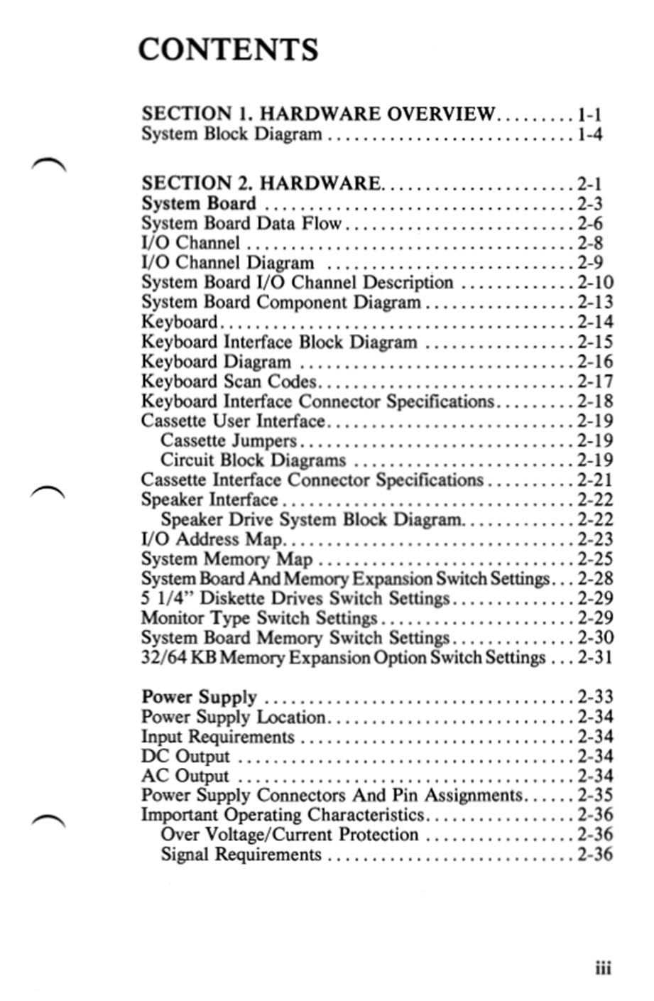
Figure 4: Table of contents from the IBM PC specification.
The designers of the IBM PC have done a good job setting up their table of contents. They start with a short section called “Hardware Overview”, which is only four pages long. At first, I was puzzled as to why they would make an entire section this short, but I understand this now as a powerful technique. The Hardware Overview section tells the reader what information they need to fully absorb before they can proceed to reading the rest of the specification. The reader mentally comes to a pause when they see that a whole section has ended, which I think would make them reflect and make sure they understood what they just read.
The second section is called “Hardware”. This is a long section with 100+ pages, and it is broken down into subsections based on major hardware components (e.g. system board, keyboard, monitor).
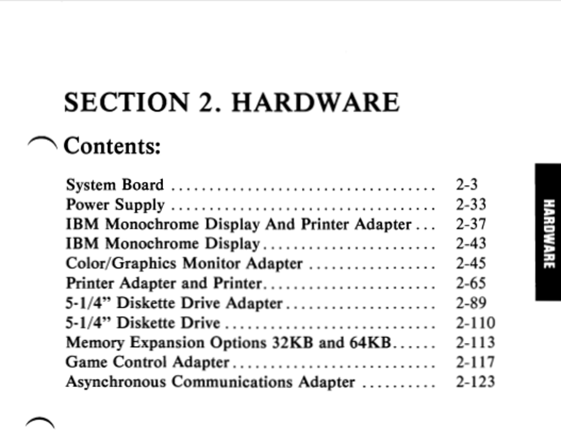
Figure 5: Subsections within the hardware section.
The third section is called “ROM and System Usage”. I like to think of this section as the “Software” section, even though it is not named as such. This section describes low-level software functions such as the BIOS, interrupt vectors, memory maps, and keyboard encodings. We can see that this section is meant for describing the interface between the hardware and software and will primarily be used by the programmers of operating systems.
When specifying a computer, a table of contents that splits the organization into hardware and software makes sense. Could there have been other ways of setting up the table of contents? Maybe. Perhaps the system board could have been a chapter on its own, since it is such an important component, and Section 3 could have been merged with the new System Board section, since BIOS and low level software run on the system board. However, this would mean that OS programmers who want to reference the specification would have to skip over detailed hardware descriptions every time they have to look up software information in the spec. Since computer engineers divide themselves into hardware and software engineers, I think it makes more sense to divide the chapters in the specification in that way too. Thinking about how your spec will be referenced by your audience is an example of the empathy that the writer needs to have towards the reader and make the spec most useful to them – an important point we will discuss further in Lesson 6.
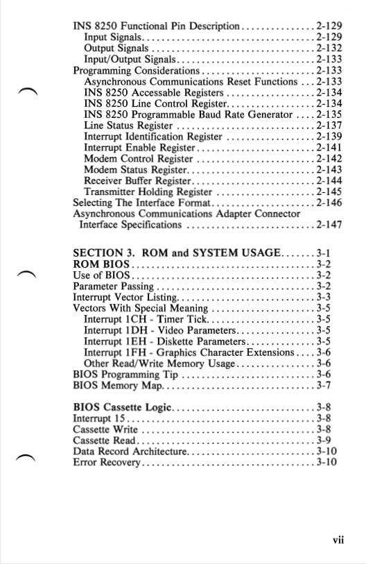
Figure 6: Another page from the table of contents.
The Preface
Even a short specification should have a preface. The preface goes hand in hand with your table of contents and is an opportunity for the writer to play the role of a wise wizard, introducing the reader to their quest. You state what this document is, who it is intended for, and what the sections and appendices are about.
The IBM PC spec has an excellent preface that succinctly introduces us to the 393-page document in front of us.
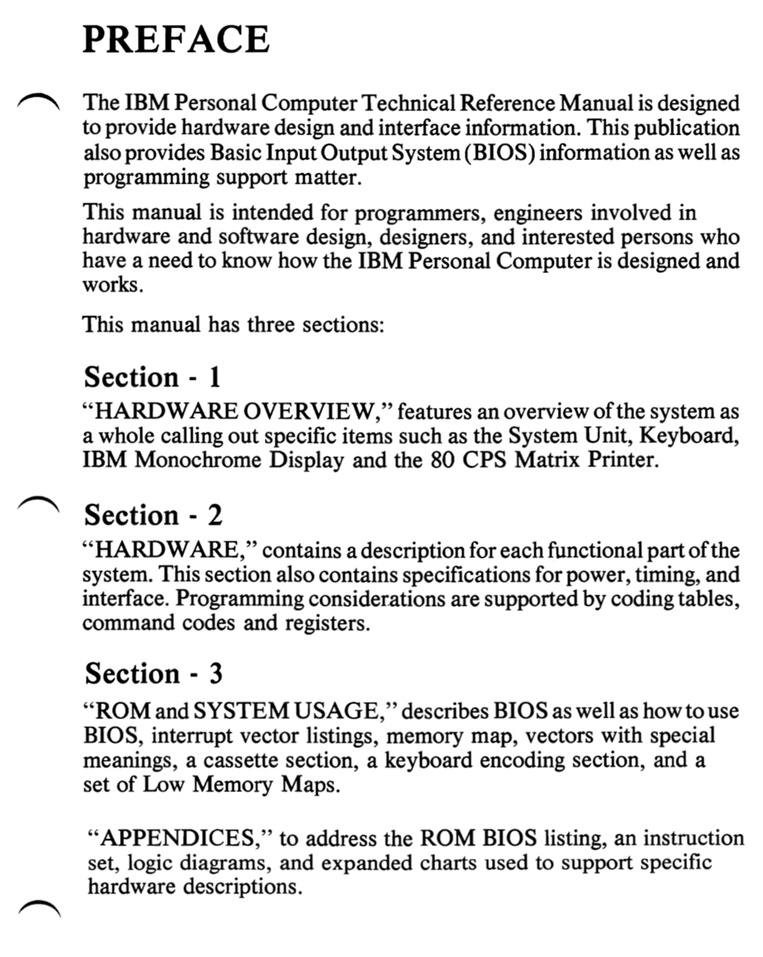
Figure 7: A preface is a great way to introduce the reader to their quest in understanding your system.
Lesson 2: Maintain a systems-centric view of your design, at all levels
We actually began discussing Lesson 2 already, when we talked about the difficulty of coming up with chapters, sections, and sub-sections in the table of contents. At the heart of Lesson 2 is the following question: how do you break down the complexity of your design, such that the specification is easy to understand for the reader?
The way human beings make sense of new knowledge is through layers of abstraction. Once those layers are identified, our brains start peeling away, and dividing and conquering the information in front of us. As the writer of the specification, you need to identify these layers of abstraction and communicate them to the reader. This can be a fine line to walk on. At every layer, you want to go into the appropriate level of detail. You do not want to gloss over details and risk being imprecise, yet you need to avoid overwhelming the reader with information that is not needed to achieve the level of understanding needed at that layer.
How did the writers of the IBM PC spec tackle this task? I identified three levels of abstraction (Abstraction Levels 0,1,2) that serve as a good example of the right level of complexity to shoot for at each level.
At Abstraction Level 0, we have the hardware overview given at Section 1. This is where the IBM PC itself is being introduced. We are being walked through the organization of the system, starting from the highest level of division possible, which is the System Unit and the Keyboard (the two visually discernable parts of the computer). We get an overview of various major subsystems, such as the monitor, the system board, and the diskette drive adapter. Notice how any of the numbers given are at the appropriate level you could imagine seeing at a specs sheet in a marketing document - 256kB storage, 160kB diskette drive, 80CPS dot matrix printer, and so on.
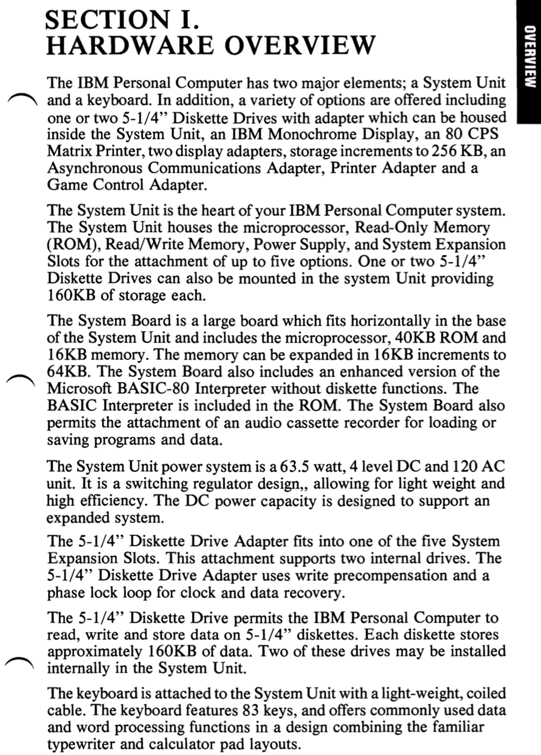
Figure 8: Abstraction Level 0, where we get an overview, and marketing-level specifications.
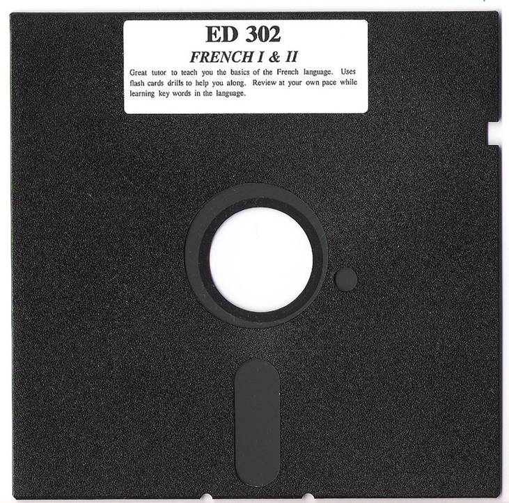
Figure 9: A 5 ¼ ‘’ Diskette. Contrary to the popular belief, this is not a 3D printed save icon 😉 Photo by Theo Curmudgeon
At Abstraction Level 1, we have the system board, which is a major subsystem with subsystems of its own. This is the level of abstraction where we start to see some real engineering information. We learn about:
-
The construction of the system board PCB (multilayer board with power and ground planes)
-
Functional subsystems of the system board (ROM, R/W, I/O etc.)
-
Type of microprocessor used, its major specifications, and its clock frequency.
-
How the system board interacts with peripherals, and its own subsystems.
This level of detail corresponds to about as much as a “power user” would like to know about their computer. The hardware knowledge needs of most software engineers writing programs for the IBM PC would also be satisfied.
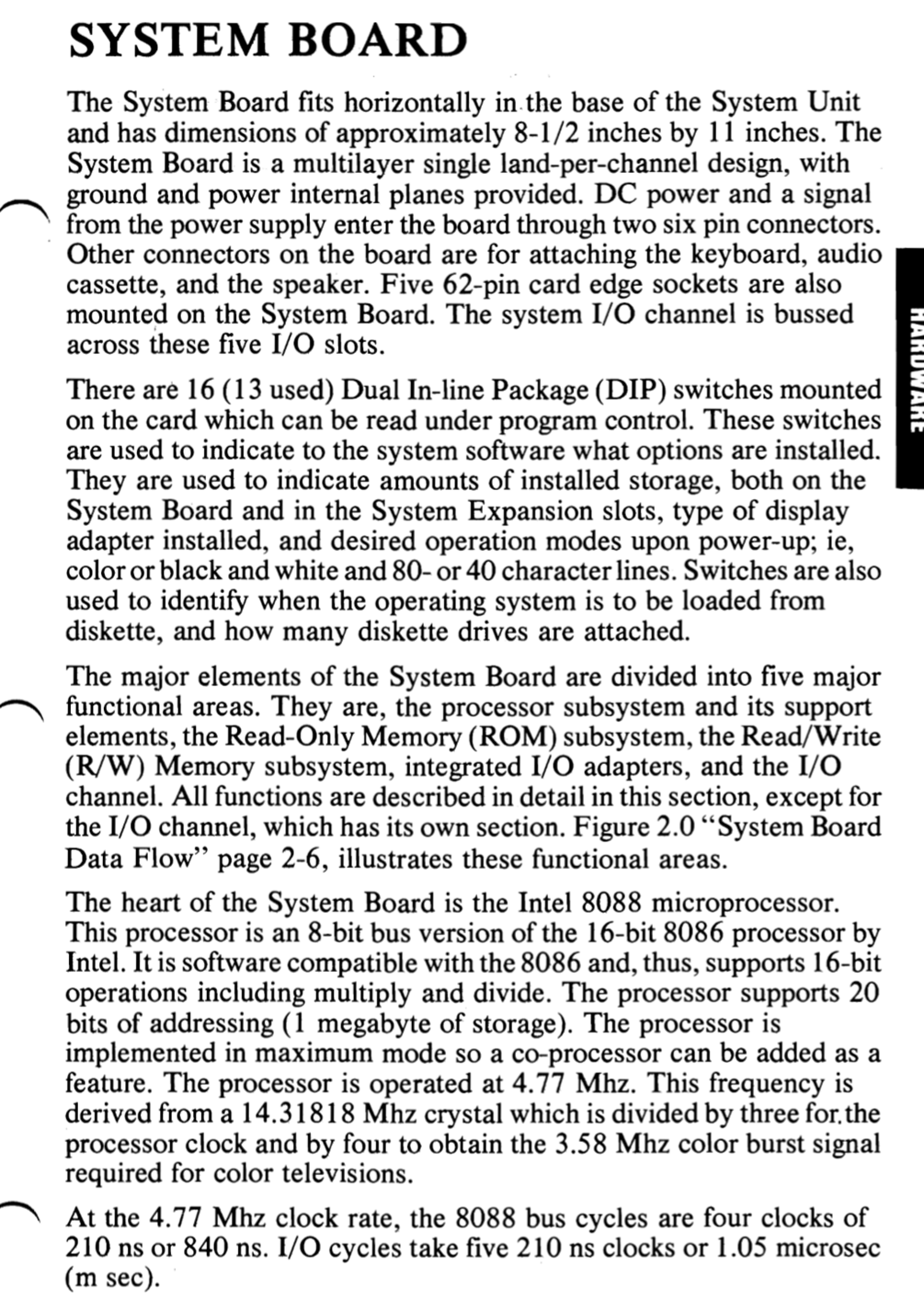
Figure 10: Abstraction Level 1, where we start getting real engineering details.
To illustrate Abstraction Level 2, I chose the Diskette Drive Adapter, which is a subsystem of the System Board. The level of engineering detail here is enhanced further, and now we are getting nuts-and-bolts electrical engineering information:
-
We learn about the types of floppy disk being used, and the encoding scheme
-
We learn that the capacity of the diskette drive is actually 163840 bytes (remember that at Abstraction Level 0 we were told that it was approximately 160kB!)
-
We learn about how analog phased locked loops are being used for clock and data recovery from the floppy drive data.
While this lesson in finding the appropriate levels of abstraction and the level of knowledge in them might seem obvious, it was one of the major challenges for me when I was writing my specification. Reviewing your specification with other engineers is key to nailing this lesson. Others with a fresh eye can point out bits of information that you left out, or places where you overshared details.
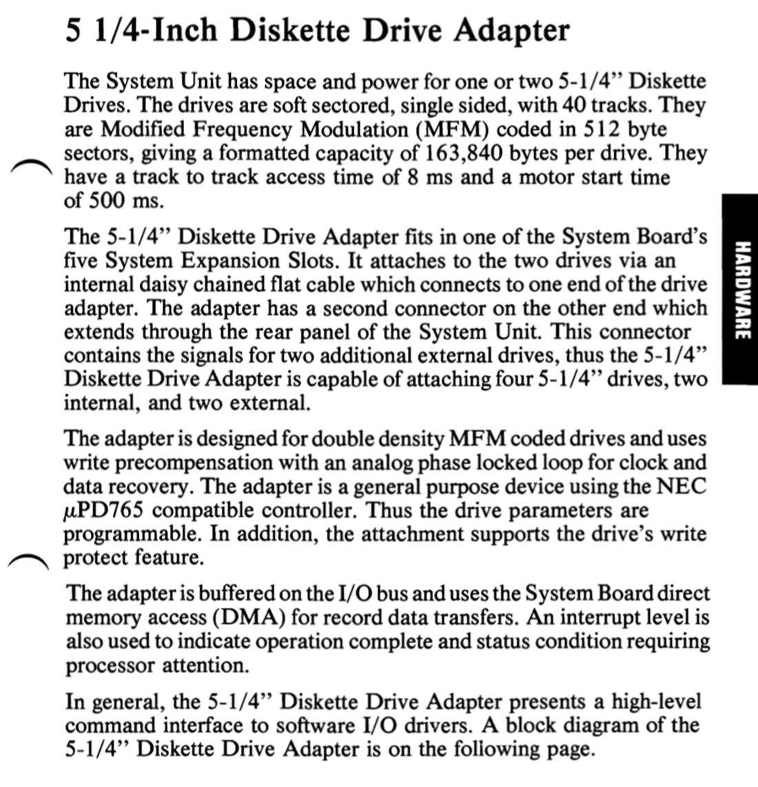
Figure 11: Abstraction Level 2. Getting even more electrical engineering details now.
What other tools does the writer have to make it easier for the reader to divide-and-conquer the complexity in the system?
Block diagrams
A system block diagram is a great thing to have in your spec. Long verbal descriptions of what a system is supposed to accomplish can get confusing very quickly, so giving your readers visual directions on how different parts of the system combine and interact with each other is a big help to them.
In the IBM PC block diagram, there is a visual sense of what each block physically looks like, further giving context to the readers. Critical information such as the wattage of the power supply, and the capacity of the memory is captured. The system board is broken into its subsystems, but the details are not overwhelming. We see that there is a “keyboard attachment”, but the system block diagram does not go into more detail, which is perfectly fine. In general, there is not much text. This is a great Abstraction Level 0 block diagram.
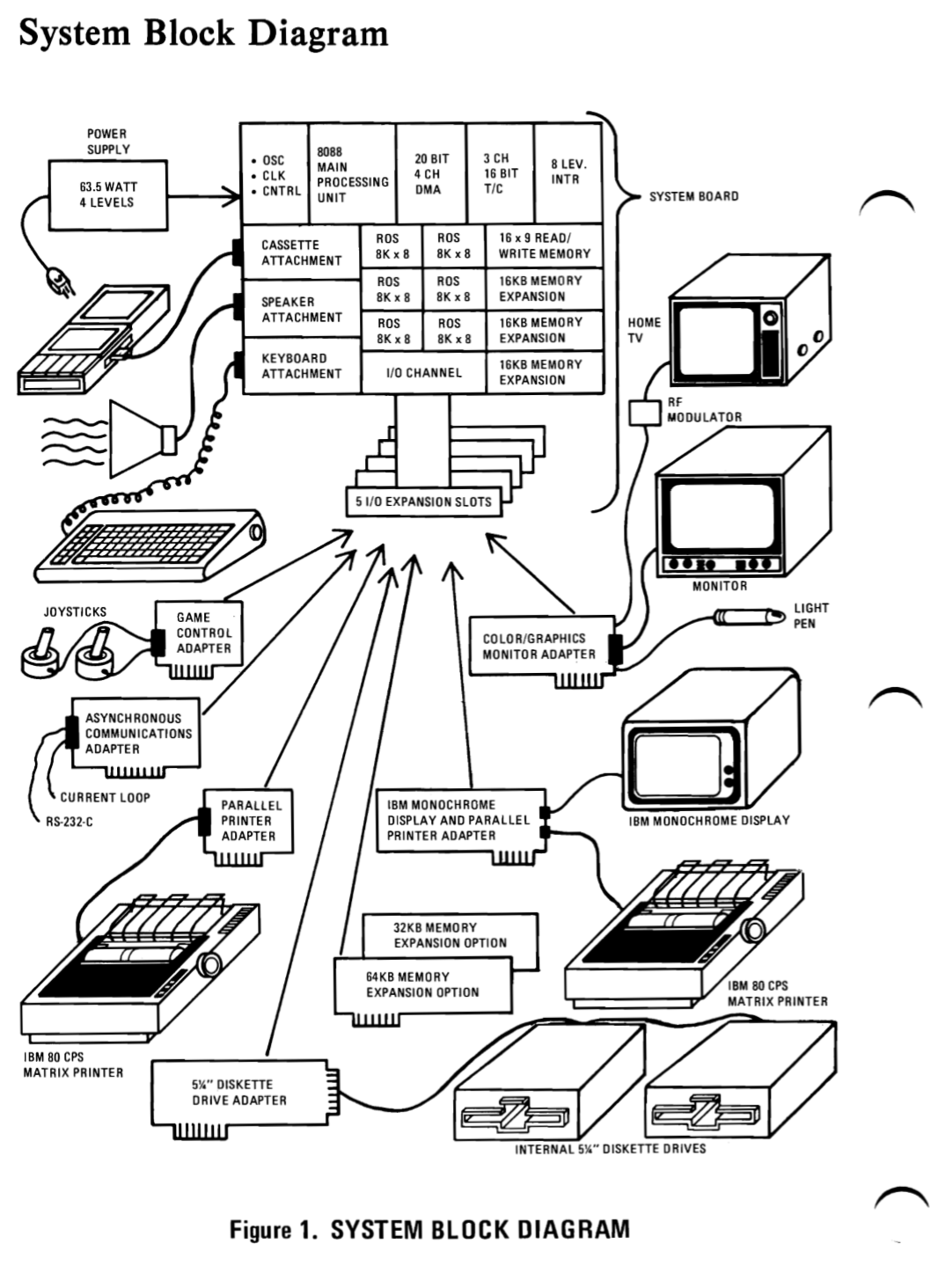
Figure 12: IBM PC’s block diagram. Easy on the eyes, and easy to understand. This is a good “Abstraction Level 0” block diagram.
The Diskette Drive block diagram below is appropriate for Abstraction Level 2. At Abstraction Level 0, we saw a cartoon circuit board of the diskette drive adapter, and now we see how the floppy controller works. Notice how we see diagrams of various electrical components such as AND gates, inverters, and decoders. This is perfect for an Abstraction Level 2 block diagram. We do not want a full schematic, but by connecting signals with AND gates the writer can express themselves more simply than using long verbal descriptions.
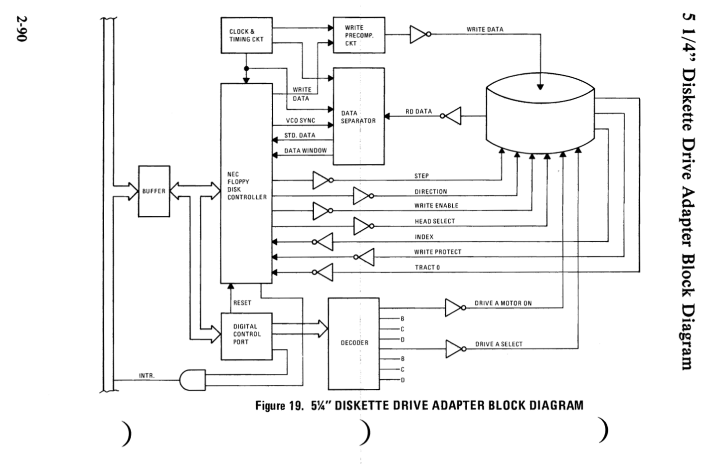
Figure 13: An “ Abstraction Level 2” block diagram for the Diskette Drive.
Coming up with quality block diagrams takes time. This effort pays off handsomely, however. The difference that an OK block diagram and a superb block diagram can make on your reader’s understanding is profound.
While a block diagram is usually a good guide for your readers, it can lead them down a path of confusion if you are not careful. Many block diagrams try to cram too much information – a common offense that has especially been made worse with diagrams that were never meant to be printed. The older block diagrams I came across during my research were hand drawn and were always meant to reside on a piece of paper. This guaranteed a certain degree of simplicity. When the writer only ever sees their block diagram on a screen, it becomes easier for them to add more and more text, and ever shrinking graphics. From there it is a slippery slope until you end up with a diagram that your reader must zoom in 400% to have any hope of making sense of it.
The worst offenders of unreadable diagrams are the Chinglish data sheets from no-name Chinese manufacturers:
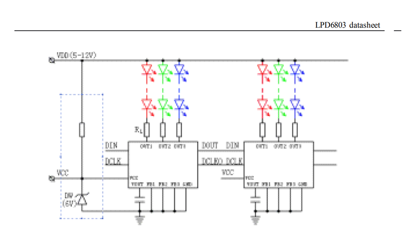
Figure 14: “Make sure to connect your pixels to ground”. [5]
Sadly, large semiconductor companies are guilty of block diagram pixel art too:
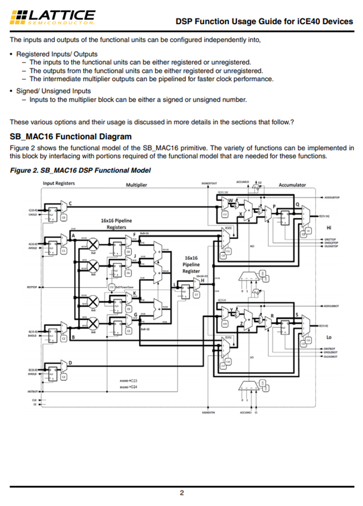
Figure 15: Whoa. There is a lot going on, let’s zoom in.
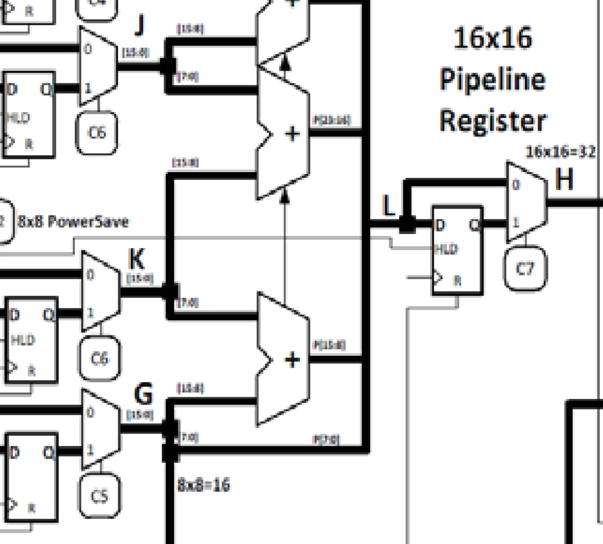
Figure 16: 16x16 = 32??? From Twitter user @oe1cxw
The block diagram is a map - a way for you to put the reader’s visual cortex into work so that they understand your system better. So, make it a good map.
Lesson 3: Clearly capture the interfaces within the design.
It is so important to describe, in detail, the interfaces between the subsystems of your design. These interfaces are prime breeding grounds for bugs, and your efforts to painstakingly specify the interactions between your subsystems will allow you to catch bugs before they have a chance to appear.
The writers of the IBM PC spec went to great lengths to capture their interfaces. Figure 17 shows how data flows within the system board. Even though making a full data flow diagram could be hard for complicated modern designs, it is worth it to add at least power trees and clock trees. The power tree shows how power flows in your design, and the clock tree shows where your subsystems get their clocks from.
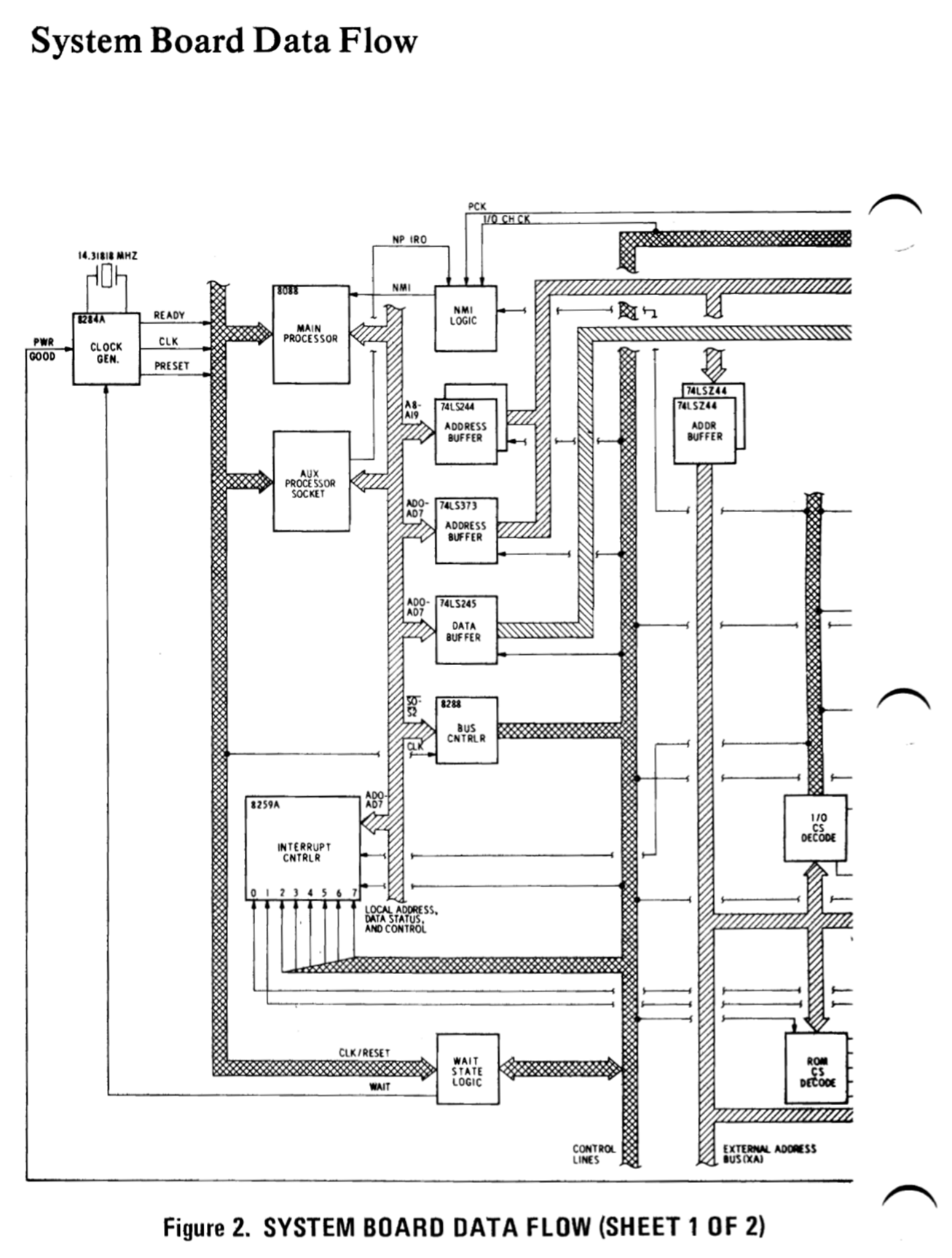
Figure 17: Capturing how data flows within the system board.
Figure 18 is a good example on how to describe signals at an interface. This is for the parallel port between the system board and the dot matrix printer. We see signal pin numbers, signal labels (labeling active low signals also with a line over the text), their direction, and their description. While not shown in Figure 18, it is described earlier in the text that these signals use TTL logic levels.
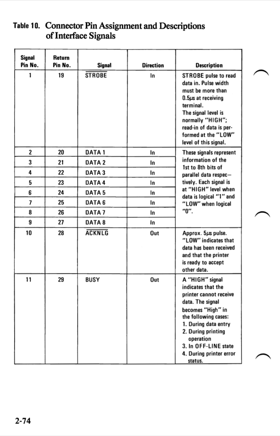
Figure 18: Parallel port signals going to the dot matrix printer are described.
Figure 19 is cool, because the Pin 1 location of the Diskette Drive Adapter is labeled by referencing to a mechanical diagram. Ask any experienced electrical engineer and they will admit to having flipped Pin 1’s on their flex cables at some point. I know I have. This sort of mistake can be embarrassing, so preparing drawings with pin labels will help you check your work.
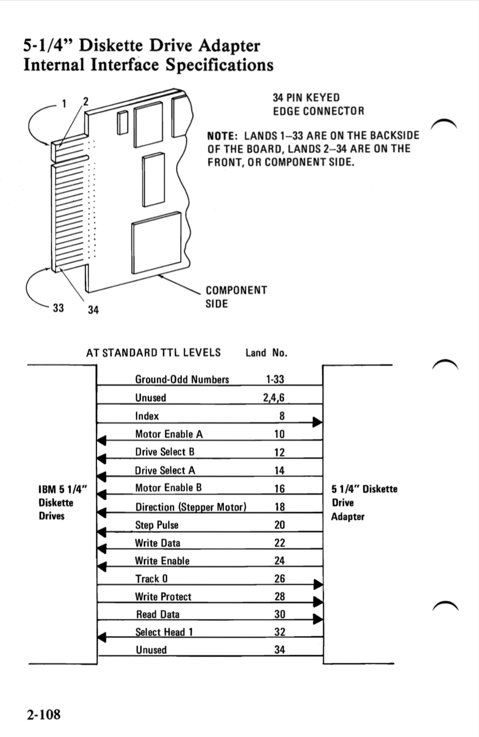
Figure 19: Illustrating your mechanical interfaces will help catch Pin 1 bugs!
Lesson 4: Do not mix implementation with specification
Now is a good time to meditate on what exactly it is that we are trying to accomplish when we write a specification.
A specification is about the architecture of an engineering system. It tells us how an overarching system emerges from numerous subsystems. For a specification to be effective, it needs to be agnostic of the implementation. This quote from the famous book The Mythical Man Month explains beautifully what we mean by the distinctness of the architecture, and the implementation (the emphasis is mine):
The separation of architectural effort from implementation is a very powerful way of getting conceptual integrity on very large projects […] By the architecture of a system, I mean the complete and detailed specification of the user interface. For a computer this is the programming manual. For a compiler it is the language manual. For a control program it is the manuals for the language or languages used to invoke its functions. For the entire system it is the union of the manuals the user must consult to do his entire job. The architect of a system, like the architect of a building, is the user’s agent. It is his job to bring professional and technical knowledge to bear in the unalloyed interest of the user, as opposed to the interests of the salesman, the fabricator, etc. Architecture must be carefully distinguished from implementation. As Blaauw has said, “Where architecture tells what happens, implementation tells how it is made to happen.” He gives as a simple example a clock, whose architecture consists of the face, the hands, and the winding knob. When a child has learned this architecture, he can tell time as easily from a wristwatch as from a church tower. The implementation, however, and its realization, describe what goes on inside the case—powering by any of many mechanisms and accuracy control by any of many. [2]
Users do not care about how features are implemented in your system. What they care is what your system can accomplish for them, which is what the specification is about. When you are writing your spec, you should not forget that you are the user’s agent. When I was writing my spec, I included a section that gave the user’s story of how they would interact with the system we were specifying.
Divorcing implementation and separation is yet another area where the IBM PC spec shines. The only place where you will find detailed schematics is the appendix. They stuck to using off-the-shelf parts as much as possible (e.g 74LS244 buffers), which helps to split specification and implementation. A common way for implementation to sneak into the specification is the usage of poorly specified, proprietary parts. These parts become black holes to the readers, which eventually force them to make frustrated calls to Field Applications Engineers supporting those parts, reducing the value of the spec document in the process.
Lesson 5: Follow good electrical specification practices
In the first three lessons, we already touched upon some good examples of how to specify electrical parameters. I praised the interface description in Figure 18, and the electrical block diagram in Figure 13. Here are some more good examples from the IBM PC spec.
Specify your off the shelf components
Off-the-shelf (OTS) components are not created equal. Capture your assumptions in the performance of the OTS components your system is using.
By not capturing these assumptions, you are exposing your spec document to any changes the manufacturer might make to the specification of the part. Even worse, your system might be relying on a property of the OTS component that was not called out explicitly on the spec, and this property might end up changing as a result of a tweak the vendor does to their manufacturing process.
Neglecting this step is a recipe for weird bugs that appear seemingly randomly during your product’s lifetime. Bugs that make poor engineers scratch their heads and yell at their oscilloscopes – “I don’t understand, we are following the spec!!”
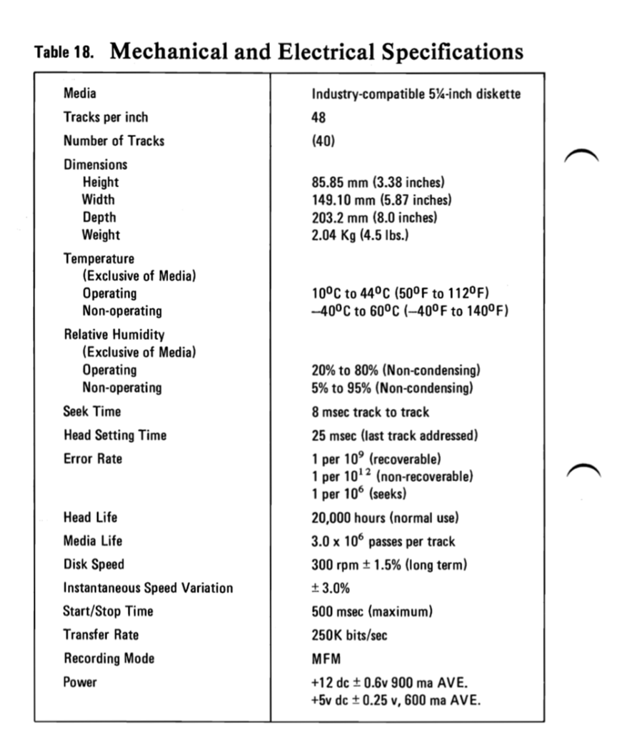
Figure 20: IBM PC designers meticulously specified their 5 ¼’’ diskettes.
Make good electrical block diagrams
We already saw an electrical block diagram example in Figure 10. Here is another in Figure 21. Notice how this diagram contains more electrical details than a typical block diagram, but it is not quite a schematic, and it does not need to be. Electrical components such as D-latches and the 74LS322 shift register are represented as functional blocks only. After understanding this block diagram, the reader will have a much easier time reading the schematic for the keyboard interface.
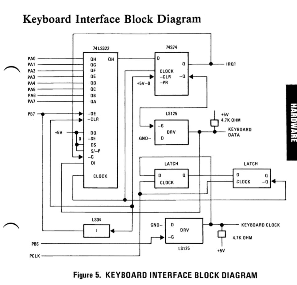
Figure 21: Another electrical block diagram example.
Include simplied schematics where needed
While you want to avoid full-blown, complex schematics in your specifications, using simple schematics made out of basic components is OK. In the joystick example above, drawing potentiometers explains to the reader how the position detection is done. It would be silly to turn a humble potentiometer into a block with three terminals and then proceed to explain its function.
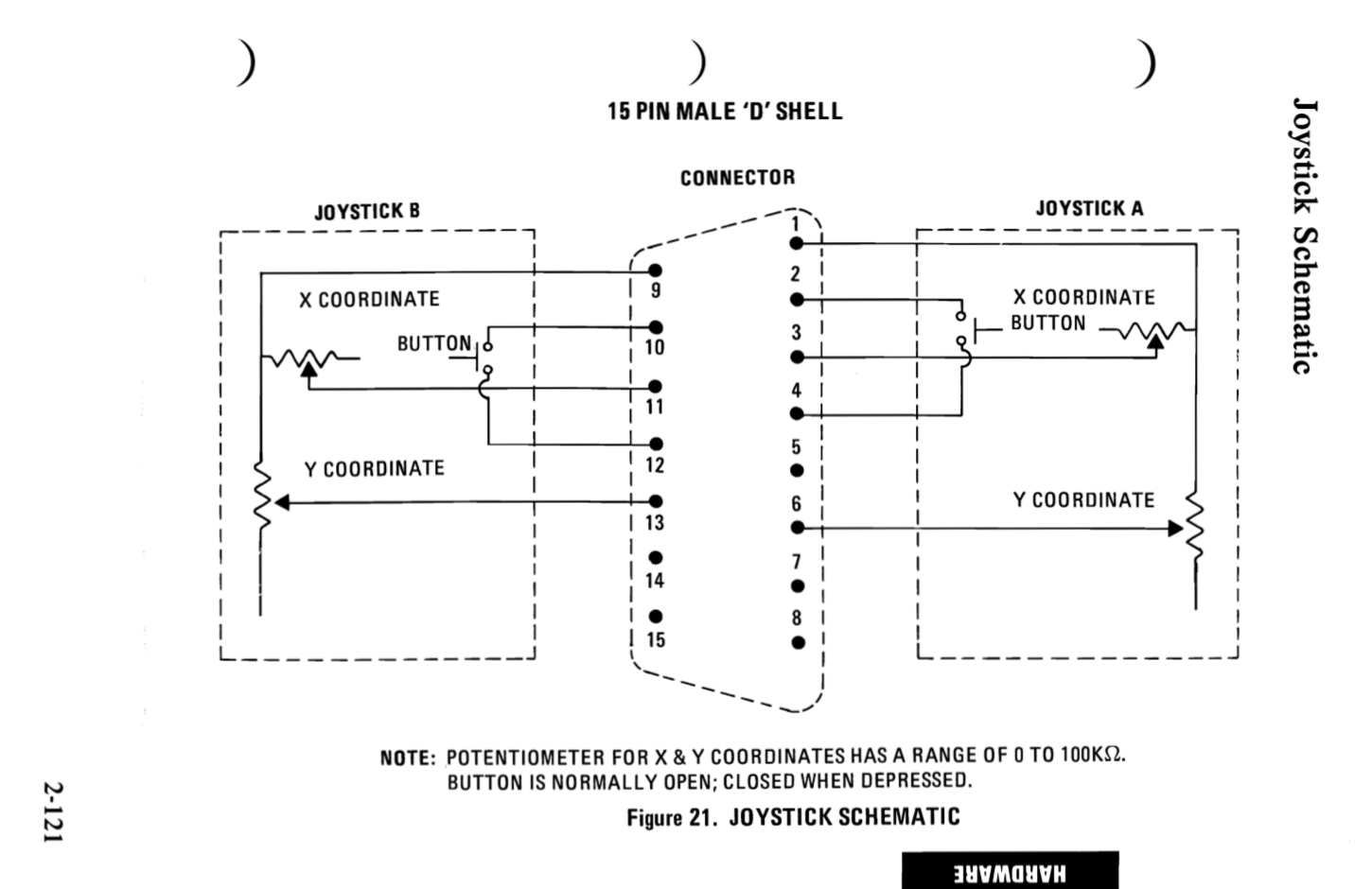
Figure 22: A simple joystick schematic. This is appropriate for a spec.
Include tolerances for the parameters you specify
State tolerances for any of the parameters you give in your document, just like in Figure 23 below.
A common mistake here is ambiguity with regard to “nominal” specs. Even datasheets from large semiconductor companies can be guilty of this. How is “nominal” defined? What operating temperature is being assumed at nominal conditions?
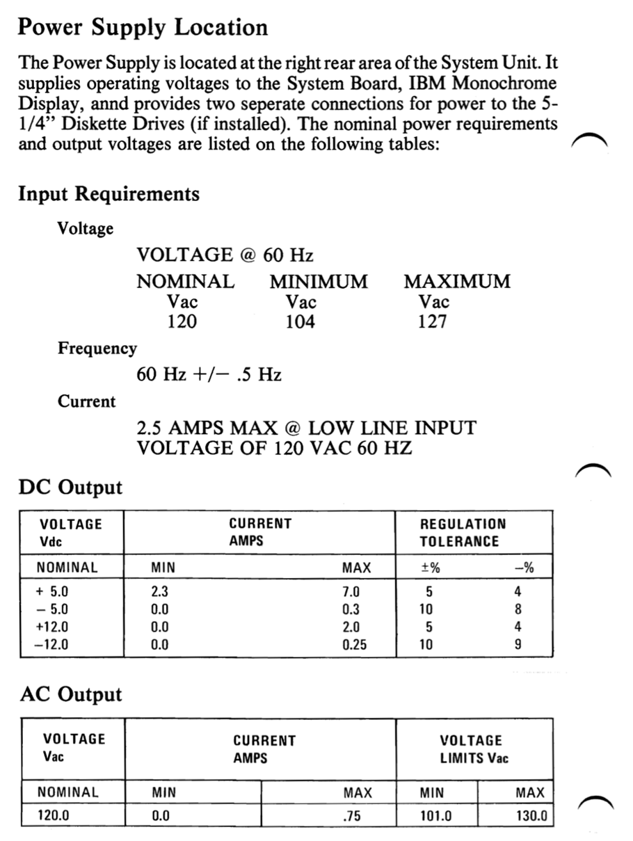
Figure 23: Specify tolerances for your parameters.
Lesson 6: Think of how you can support the reader
The reason you are going through all this effort of writing a specification document is the reader. Whatever you do, it is important that you try to make the reader’s job as easy as possible. This will determine whether you are successful or not as the writer of the specification document. A common complaint I see about writing specifications is “well nobody is going to read it anyway”. This attitude will become a self-fulfilling prophecy for any piece of writing, because the writer will not put in their best work, and they will not have empathy with the reader.
To give your spec a chance to be read widely, you need to ensure the you have grammar and spelling nailed, and that the document looks good. You do not need to spend five hours trying to find the perfect LaTeX package (cough cough) but do make the document clean and approachable.
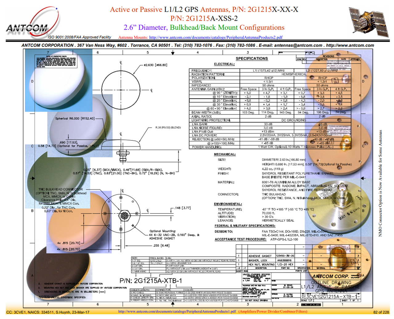
Figure 24: Please promise me you won’t do this. [3]
From my own experience as a reader of specs, adding the sections I listed below will greatly increase the value of your specification document.
The Appendix
The appendices of your specification are a chance for you to present information that while not a part of the specification itself, would be useful to the reader. For the IBM PC spec, the appendices included the source code of the BIOS, the Intel 8086 assembly instruction set and electrical schematics.
Some good ideas for appendices:
-
Implementation information, such as electrical schematics or reference designs.
-
Quick reference information. An example of this is how the IBM PC spec included the assembly instruction set for the Intel 8086.
-
Any checklists, quick start guides, or recommended design workflows for designers that would be working with your system.
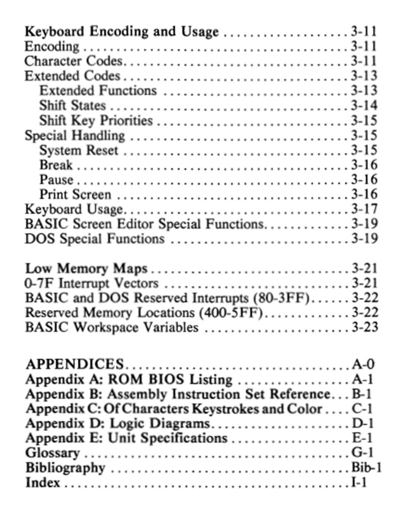
Figure 25: Appendices included with the IBM PC spec.
The Glossary
The glossary makes sure that the reader and the writer are on the same page when it comes to the terms used in the document.
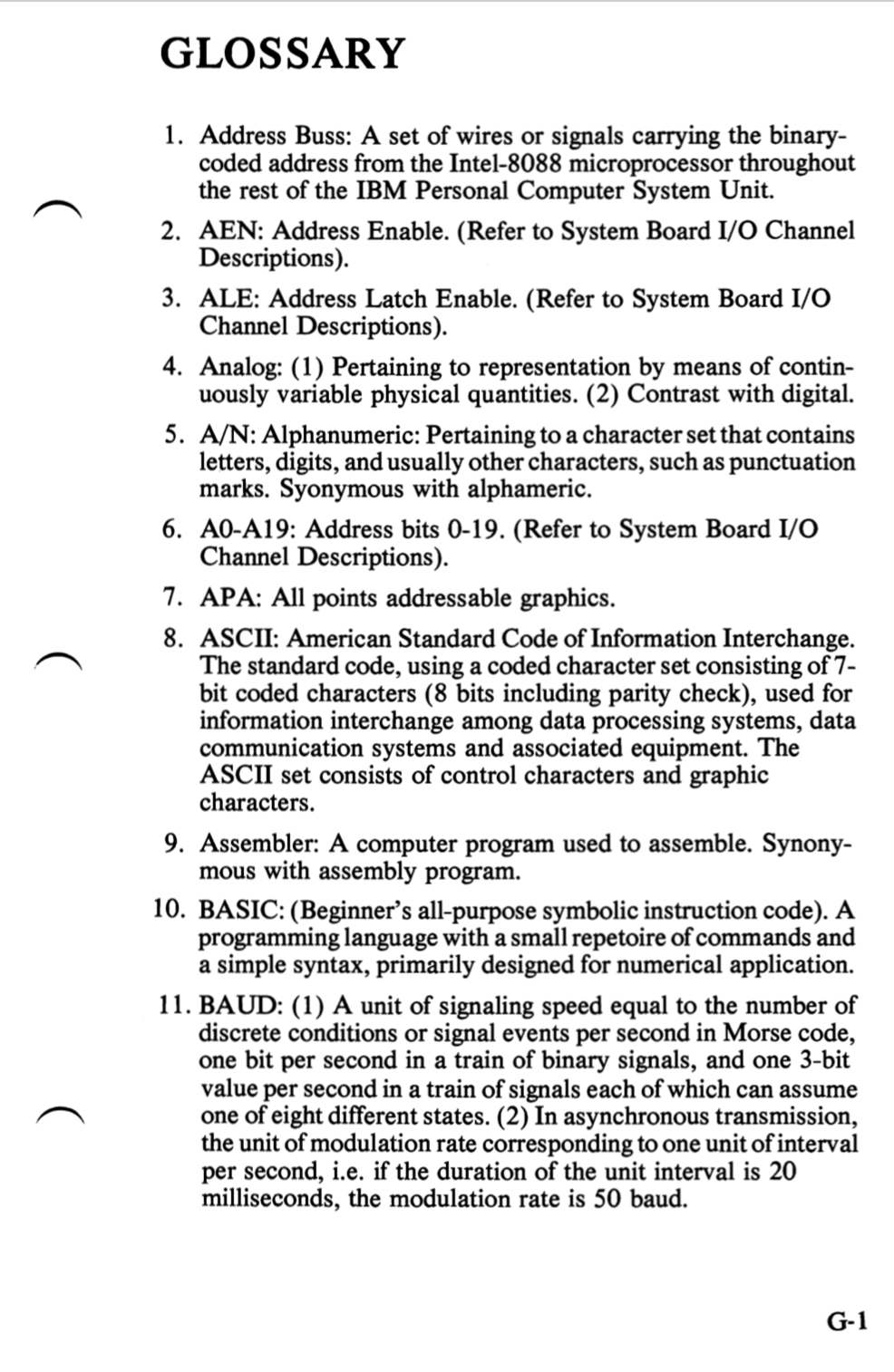
Figure 26: Glossary from the IBM PC spec.
The Bibliography
Not much to say here. Just like your college papers benefited from bibliographies, your specs could use them too. If you are linking to websites in your spec, I would suggest saving an offline copy of the website you are linking to, because it is only a matter of time before link rot happens.
Revision Tracker
Continuously track any changes you make to the document to make sure there are no issues down the line in the field with conflicting information from different document versions.
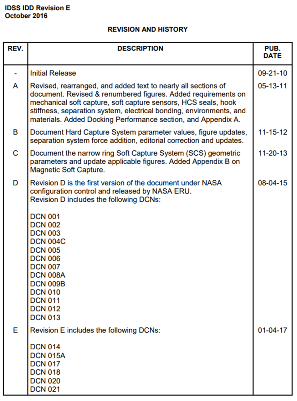
Figure 27: Revision tracking from the International Docking Adapter specification. [4]
List of Figures and Tables
List of Figures and List of Tables are great for easy reference.
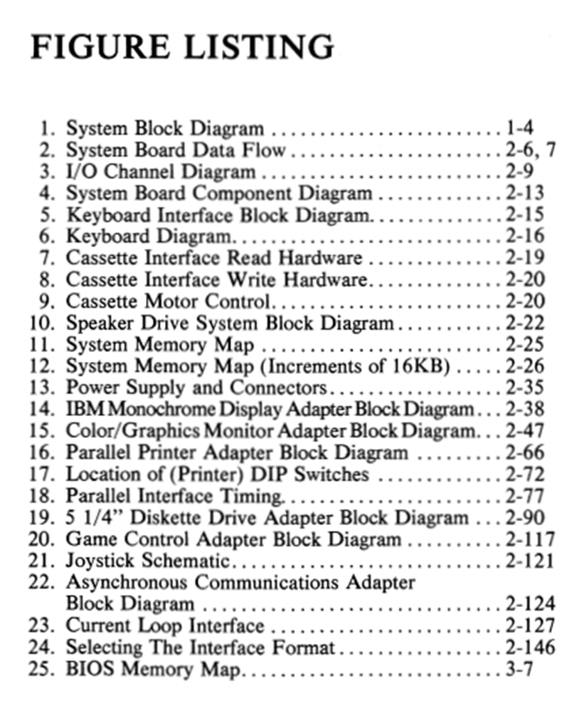
Figure 28: List of figures from the IBM PC spec.
Wrapping up, and further resources
Let us recap the lessons I learned from the IBM PC specification:
Lesson 1: Write your table of contents carefully.
Lesson 2: Maintain a systems-centric view of your design, at all levels.
Lesson 3: Clearly capture the interfaces within the design.
Lesson 4: Do not mix implementation with specification.
Lesson 5: Follow good electrical specification practices.
Lesson 6: Think of how you can support the reader.
I hope they will be useful in nailing down the Huaqiangbei Test. Here is a list of further resources to check out.
Linear Technology datasheets
I spent the summer of 2015 interning at Linear Technology (before it was acquired by Analog Devices) and can attest that LT’s designers take great pride in their datasheets. During my internship, my mentor was in the process of writing a datasheet, and I saw firsthand how much effort and care he was putting into his draft. LT and AD datasheets are hailed as some of the best in the industry for a good reason. EEs always say that they would love to use LT parts just for the sake of the datasheets, if BOM costs were no object. 😊
While we are talking about Linear Technology, here is another good power tree example from them.
Industry specs
Many of the industry standard EE specifications are public. Studying industry specs also helps with interviewing, since interviewers love to ask about how industry standard buses work (e.g I2C and SPI).
NASA specs
NASA and many of the other organizations in the aerospace industry publish their specs, which can make for great learning material. I especially like the International Docking Adapter specification, which specifies how spacecraft need to have their docking interface built in order to attach to the International Space Station. It is a great example of how to specify interfaces between systems.
Article series
This was the first installment in my article series on topics I wish I had learned in electrical engineering school. There will be more articles to come. The next one will either be about the basics of flexible circuit boards, or tips for interviewing for EE jobs. Stay tuned!
References
[1] Laws of Tech : Commoditize Your Complement
[3] Antcom L1/L2 GPS Antennas.
[4] International Docking Standard (IDSS), Interface Definition Document (IDD), Revision E, 2016.
[5] Documenting Poorly Documented LED Strips